For many years, finite element modeling has been the job of a specialist; the tools used to perform even simple finite element analysis have been complex enough to require a subject matter expert. This is primarily due to the complex, difficult to understand graphical user interfaces of these products. The job is made further difficult to perform due to the requirement of advanced engineering subject knowledge by the analyst.
Can a mechanical designer who uses CAD tools to create engineering drawings be trained to perform engineering simulations?
In today’s product availability scenario, the answer is “yes.”
A CAD designer using CATIA can create and execute simple finite element models within the CATIA environment by using CATIA workbenches that have been developed for simulations. This makes it intuitive and easier for designers to ensure that their parts meet their design requirements.

How the simulation methodology gets simplified using designer level tools
- No need of an expert level analyst tool to perform simple finite element simulation.
- No need of manual data transfer between design and analysis departments.
- No need of geometry clean up tools to fix data translation errors.
There are obvious benefits to adopting this simplified approach that integrates the design and analysis environments. The designer can predict design problem early in design process; subsequently the designer can check various alternatives of design in less time. This is primarily due to the tight integration of designer level tools with knowledge based engineering that allows the designer to deliver better product in less time.
Part Level Simulation
From a geometrical perspective, the simulation model can be generated at part level to begin with. The native integration within CATIA allows users to perform stress, displacement, and vibration analysis at any time in the design process, allowing more accurate sizing of parts and fewer design iterations. Individual parts consisting of solid, surface, and wireframe geometries can be analyzed under a variety of loading conditions. The analysis specifications, such as loads and restraints, are associative, with the design allowing users to perform analyses quickly and easily. These specifications are then automatically incorporated into the underlying finite element model, meaning that users do not have to work directly with the finite element model. “Virtual parts” allow items like forces, moments, and restraints to be easily modeled without having to have a detailed geometric representation.
Standard reports can be automatically generated in HTML format, providing clear and detailed information about the results of the analysis, including images associated with the computations. These reports can be used to document the analyses that have been performed and to communicate the results of the analysis to other stakeholders in the organization. CATIA V5 Analysis users benefit naturally from the overall PLM solution provided by Dassault Systèmes, including ENOVIA V5 for data and product lifecycle management. CATIA V5 Analysis users can store, manage, and version all the data associated with their product’s simulation and share the information within the extended enterprise. This unique capability allows collaboration and provides access to advanced PLM practices such as concurrent engineering and change management.

Assembly level simulation
If the concept of virtual parts does not hold good anymore and the complexities of various parts interacting with each other make assembly level simulation mandatory, it is possible to create analysis models for assemblies as well. The analysis of assemblies, including an accurate representation of the way the parts interact and are connected, allows for more realistic and accurate simulation. The designer does not have to make simplifying assumptions about the loading and restraints acting on an individual part. Instead the part can be analyzed within the environment that it operates with the loading automatically determined based on the way the part is connected to and interacts with surrounding parts.
The various types of connections that can be modeled include bolted connections, welded connections, pressure fitting connections, and many more. To make the job further easier for the designer, these connections can be defined using assembly level constraints that already exist in the CAT Product model. Once the design changes, the associated assembly constraints as well as corresponding FEA connections get updated, thereby creating an updated FEA model that is ready for analysis.
Concurrent engineering made easier
The “assembly of analysis” capability enables concurrent engineering. For example, the various parts in an assembly can be modeled and meshed separately by different users. They can either use the CATIA V5 meshing tools or import orphan meshes (meshes that don’t have any geometry associated with them) developed outside of CATIA Analysis using a variety of different modeling tools. The user responsible for analyzing the assembly can consolidate the different meshes, connect the parts, apply the loading specifications, and run the simulation. This can significantly reduce the turnaround time when analyzing large assemblies, particularly since some of the parts may have already been analyzed and therefore, the analysis models would already be available.

Extended solver capabilities
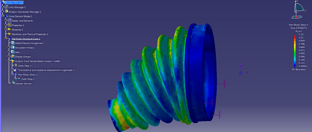
The basic level FEA solver present in the CATIA designer workbench is called the “Elfini” solver and can model only simpler physical problems such as linear materials, small deformations, small rotations and bonded contacts; real life problems can be much more complex and may necessitate the need of an advanced solver. To address such scenarios it is possible to include the well known non-linear solver Abaqus into the CATIA designer environment; it can model the effects of geometric nonlinearity, such as large displacements, and allows nonlinear materials to be included, such as the yielding of metals and nonlinear elastic materials like rubber. It also offers more advanced contact capabilities including the ability to model large relative sliding of surfaces in contact.
The Abaqus capability enables the effect of multiple steps to be analyzed, where the loading, restraints, contact conditions, etc., vary from one step to the next. This powerful technique allows complex loading sequences to be modeled. For example, a pressure vessel might be subjected to an initial bolt tightening step, followed by internal pressurization, and conclude with thermal loading.


Leave a Reply