How to Place a 3D Annotation Note Inside a Box in PTC Creo
In this i GET IT Tech Tip, we will show you how to place a 3D Annotation Note inside a box.
This methodology will create a note containing a digit inside a box and then by referring to that digit i.e. the Note Number, we will place additional long text which will explain about what actions are supposed to take place at the locations shown with the notes.
This is a small topic from our Essentials Training Courses for PTC Creo – i GET IT (myigetit.com).
Watch the Featured Tech Tip Video and Subscribe to our YouTube Channel if not Subscribed to get Notifications.
If you have i GET IT subscription you can download the part files from i GET IT’s webapp’s Tech Tip section refer fig.

Our Objectives to achieve 3D Annotation Note would be the following –

In this Combined State, we need to create a note indicating the definition of the holes which are to be created at the four HOLE_PLACEMENTS locations.
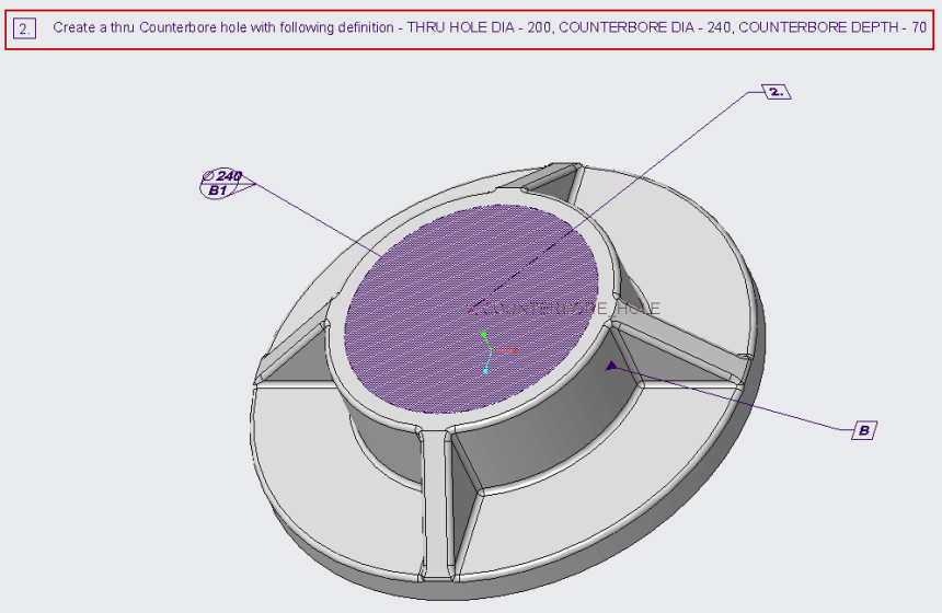
In this Combined State, we need to create a note indicating the definition of COUNTERBORE_HOLE.

Now, Observe below steps to achieve the required result –
Step 1

Activate the Combined State ‘Threaded_Holes’ and then activate the Annotation Plane named as ‘CUSTOM’.
Step 2
Create a Leader Note by taking a reference of the datum point ‘HOLE_PLACEMENT1’

Step 3

Type in following text in the Leader Note – ‘@[1.@]’
Step 4
Select the ‘Editor’ command from the ‘Text’ group of ‘Format’ tab

Step 5

A command prompt window and notepad window will open as Figure 7.
Step 6
Close the notepad window and observe the change in the Leader Note display as shown in Figure 8.

Step 7

Change the Annotation Plane to FLAT TO SCREEN
Step 8
Create an Unattached Note with the same text again – ‘@[1.@]’

Step 9

Now the Unattached Note should look as Figure 11.
Step 10
Create one more Unattached Note besides the previous note as shown and then select the ‘Note from File’ option

Step 11

Select ‘Note_1’ from the Working Directory and click ‘Open’
Step 12
Observe the explanatory note created for the four datum tag locations indicated by the note 1

Step 13

Add leaders to the first note by referencing the remaining three datum tag locations as shown in Figure 15.
Step 14
Activate the ‘Counterbore_Hole’ Combined state and then activate the ‘RIGHT’ Annotation Plane

Step 15

By referring to the previous steps, create a Leader Note as shown in Figure 17.
Step 16
Activate the ‘FLAT TO SCREEN’ Annotation Plane and create an Unattached Note as shown in Figure 18.

Step 17

Create another Unattached Note besides the previous note with ‘Note from File’ option and select ‘Note_2’ as the input file.
For more tech tips and in-depth eLearning for PTC Creo, including new courses on other design solutions, please visit https://www.myigetit.com to explore more information or Just choose appropriate subscription plan to get started! If you should have any questions, please reach out to iproducts@tatatechnologies.com for help.

Pingback: HOW TO PLACE A 3D ANNOTATION NOTE INSIDE A BOX IN PTC CREO – PTC Creo Tips