Recently we posted “How To Create Miter Joint Trim for Weldments in SOLIDWORKS” in which we know that Welded Joints aka “Weldments” is one of the process used to assemble the components/parts. In this blog you will know how to define Connection Elements for weldments and structural systems in SOLIDWORKS, and then insert them into a structural part.
Follow below video and steps to know how to define Connection Elements for weldments and structural systems –
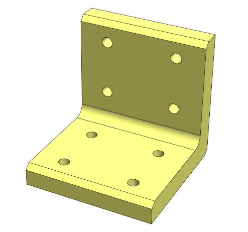
In this Tip, I’ve created an L-bracket with some pre-drilled holes, along with a few different configurations of the part.

To create a Connection Element from it I’ll activate Define Connection Element from the Command Search field.
For its References, I’ll choose a Generic placement type, select the two back faces for the Primary and Secondary References, and then select the Right plane from the feature drop-down for the Tertiary Reference. Ensuring Coincident is selected for optional mate types.


I also wanna propagate the holes on the bracket to any adjoining structural members, so I’ll select the two cut-extrudes for Feature Propagation, and then click OK.
The Connection Feature is now displayed in the Feature Tree and can be edited at any time


Next, I’ll need to save this part in the correct location so it can be inserted into a structural model. Note that I’ve updated the file location for connection elements to a new folder in my design library.
There must be at least one subfolder within the top-level folder where you’ll save connection element parts. Each subfolder within the top-level location will be the “Standard” you select when inserting connection elements, such as ANSI Inch or BSI. The models within these folders will be the “Type” of connection selected, while any associated configurations will be the “Size” selected for the connection.

With the Insert Connection Element command active, SOLIDWORKS automatically populates the connection Selection options based on my location file structure.


I’ll define the connection I wanna insert, and then use the reference entities to place the connection in the model.
I also wanna select the two beams for the Cut Scope propagation before clicking OK.


As you can see, the holes have successfully propagated through each beam
And I can always go back and edit the feature to try a different configuration or placement if desired.

About i GET IT
i GET IT is our Tata Technologies eLearning solution designed to teach engineers how to be better in using today’s leading MCAD (Mechanical Computer Aided Design) applications and design skills.
For more tech tips and in-depth eLearning for SOLIDWORKS, including this and new courses on other design solutions, please visit https://www.myigetit.com. You can sign up and get FREE Subscription when joining through SkillAdvisor to get our informative Newsletter.
Start your upskilling journey!
If you should have any questions, please reach out to iproducts@tatatechnologies.com or igetitsocial@tatatechnologies.com for help.


Leave a Reply