Overview
In this Tech Tip, we will explain about Advanced options in ‘Shell’ feature. We will see in detail how to exclude some unwanted surfaces from the definition of ‘Shell’ feature.
The User Case
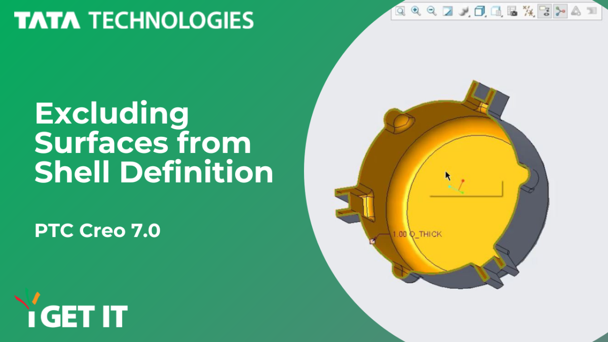
In following figure, a Shell type feature is created and the bottom surface of the flange is selected as ‘Removed Surface’. By default, the Shell feature has removed the entire bottom surface of the flange and thus the circular and C shaped protrusions have also been hollowed with a thickness of 1 mm. Due to the dimensions of circular and C shaped protrusion, the maximum applicable thickness of the Shell feature is restricted to 2 mm.
Now we need to exclude the circular and C shaped protrusions from the Shell definition and in doing so, we need to increase the thickness of the Shell feature to 5 mm.

Please follow below steps to achieve the required result –
Step1:
Edit the definition of ‘Shell 1’ feature from the Model Tree


Step 2:
From the ‘Shell’ dashboard, select the ‘Options’ tab and then click on the ‘Excluded Surfaces’ collector –
Step 3:
Rotate the model as shown and then select following surface from the C shaped protrusion as ‘Individual Surface’


Step 4:
Press SHIFT key on the keyboard and then select the top model surface as shown. This will complete the selection of ‘Seed and Boundary Surfaces’
Step 5:
Click on ‘Details’ option from the ‘Options’ tab of ‘Shell’ dashboard –


Step 6:
Click on the ‘Excluded Surfaces’ set from the ‘Surface Sets’ dialog box
Step 7:
Select following surfaces as the surfaces to be excluded from the collection of Seed and Boundary Surfaces – The two surfaces of outside round from the flange, the two cylindrical surfaces along the flange periphery and the bottom flat surface of the flange. These excluded surfaces will be shown in green color


Step 8:
Click ‘OK’ in the ‘Surface Sets’ dialog box and then observe the resulting geometry. Observe that now the circular and C shaped protrusions are no longer made hollow
Step 9:
Edit the Shell thickness value to 5 and then complete the Shell feature


Step 10:
Observe the resulting geometry with the circular and C shaped protrusions excluded from the Shell definition and the resulting hollowed geometry with a higher thickness of 5 mm
About i GET IT
i GET IT is our Tata Technologies eLearning solution designed to teach engineers how to be better in using today’s leading MCAD (Mechanical Computer Aided Design) applications and design skills. For more tech tips and in-depth eLearning for PTC Creo, including this and new courses on other design solutions, please visit https://www.myigetit.com to explore more information. You can sign up and get FREE Subscription of our Newsletter and there are subscription plans to get access and start your upskilling journey! If you should have any questions, please reach out to iproducts@tatatechnologies.com or igetitsocial@tatatechnologies.com for help.


Leave a Reply