
As an FEA analyst, you are likely losing too much of your time in CAD repair.
If you are an experienced FEA analyst, you must have come across following types of situations often while meshing your models:
“I create 3D geometries in CAD uniting together several surfaces so that the CAD modeler itself sees one unique surface; however, whenever I export it as a .sat, .stp or even binary file for Parasolid and then import it into the FEA pre-processor, I again see all those surfaces that are not supposed to be there.”
“For some parts I am extruding surfaces to solids, and for some parts I am building solids out of intersecting surfaces. All in all, it is a kind of a box structure with a hole on one side. I started importing it to GUI part by part, and as soon as I have top and bottom plate and two sides, the meshing fails. How did you exactly resolve this meshing problem?”
The FEA user community knows that most of the user interfaces available for finite element analysis are good for FE modeling only – they are not expert CAD modelers. It often happens that the CAD model created is not free from defects from a meshing perspective. The most common problems are duplicate edges, gaps, silver surfaces, unnecessary patches, etc. The problem is often more severe if a CAD model is first translated to a neutral format such as .sat, .iges, .step files before being imported into the FEA pre-processor; the defects are generated during the translation. In many other cases, the repairs made in the CAD model are not propagated into FEA modeler. The only option left is to repair the geometry in the FEA model itself, but the repair tools required often don’t exist in these user interfaces.
One-click model transfer from CAD to FEA without any neutral file format
For Abaqus users, there is great news: the Abaqus CAE pre-processor now has associative interfaces for CATIA, ProE and SOLIDWORKS.
The CATIA V5 Associative Interface allows you to transfer CATIA V5 Parts and Products into Abaqus/CAE using associative import. Materials and publications assigned to the CATIA V5 model are also transferred to the Abaqus/CAE model as material and set definitions respectively. In addition to associative import, the CATIA V5 Associative Interface allows you to directly import the geometry of CATIA V5 models in .CATPart and .CATProduct format into Abaqus/CAE without any intermediate neutral files. The following options are available with CATIA V5 associative interface:
- Automatic associative import is a powerful tool that allows you to quickly transfer models from a CATIA V5 session to an Abaqus/CAE session while both programs are running simultaneously on the same computer. After the model has been transferred, you can continue to make design modifications in CATIA V5 and propagate these modifications to the Abaqus/CAE model with a single mouse click; any of the features that you created in Abaqus/CAE – such as partitions, loads, boundary conditions, sets, and surfaces – are regenerated each time you import the modified model from CATIA V5 to Abaqus/CAE.
This feature is of great use while doing design of experiments simulations. This is because the user can update the existing mesh and loading scenarios on the new design variant. It is not required to define the FE model all over again.


- The CATIA V5 Associative Interface also allows you to modify parameters defining CATIA geometry features – such as a hole radius or an extrusion length – from within Abaqus/CAE. The updated parameters are propagated to both the CATIA model and the Abaqus/CAE model.
- If CATIA V5 and Abaqus/CAE are not running concurrently, or are running on different computers, you can use manual associative import. Using the CATIA V5 Associative Interface plug-in, you can save an assembly (.eaf) file to a specified location. You can import the model into Abaqus/CAE, or use the assembly file to update an existing model in Abaqus/CAE at a later time. In addition, manual associative import can be used to perform an associative import across Windows platforms (for example, from CATIA V5 running on a 32-bit Windows machine to Abaqus/CAE running on a 64-bit Windows machine).
- Direct import is a non-associative import that does not require the use of the CATIA V5 associative Interface plug-in. The geometry of models saved as standard CATIA V5 Part or product files can be imported directly into Abaqus/CAE. You cannot use direct import to update existing models in Abaqus/CAE, but you can use direct import to transfer model geometries across 32-bit and 64-bit Windows platforms. The ability to move between associative import and direct import provides flexibility within the enterprise or across the supply chain in the approach that you use for transferring models from CATIA V5 to Abaqus/CAE.


ASSOCIATIVE INTERFACE PRODUCTS COMPARISON
The following diagram shows a comparison of available functionalities between different associative interfaces: CATIA, ProE and SOLIDWORKS.
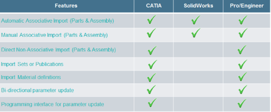

The user should also notice that while CATIA, ProE and SOLIDWORKS are unit sensitive CAD platforms, Abaqus CAE is a unit neutral FEA pre-processor. In the case of dimensions, the transfer is limited to the number only without taking the associated unit into consideration. For example, a CATIA part file has a part with dimensions 20mm x 10mm. If the displayed units in CATIA are mm, then the corresponding part dimensions in Abaqus CAE are 20 x 10. However, if the units in CATIA are changed to cm and then model is transferred, the corresponding part dimensions in Abaqus CAE are 2 x 1. There is also a compatibility matrix between the CATIA version and Abaqus CAE version as follows. The same kind of matrix exists for ProE and SOLIDWORKS associative interfaces as well.


I hope this has been an informative breakdown. Leave a comment if you have any questions or additional thoughts.